Recently I decided it was finally time to upgrade my gaming computer. I had skipped over Intel’s recent spate of chipsets, as well as Windows Vista, so my computer – still based on the Intel x975 chipset and Windows XP Pro – was definitely in need of an upgrade.
This is the second post documenting my upgrade to an Intel Core i7 Lynnfield system. In my first post I discussed the components I selected and why. In this post I’ll talk about assembling the system and the challenges I encountered. In my final post I’ll cover my attempts at overclocking the new system.
The Build
I like to build systems outside of the case. Then, when I’m sure everything is running well, I’ll place the components in the case and dress up the wiring (See Figure 1). Similar to other motherboard manufacturers, Intel has finally taken to mounting the SATA II ports horizontally, facing the back of the case, instead of vertically. Good thing too because the video card would likely have prevented me from using the first couple of ports. I’m using two 36GB Western Digital “Raptor” drives configured for Raid 0 to hold the OS. I placed these on SATA ports 0 & 1. I also have a pair of 74 GB Raptors will be configured for Raid 0, but these will become my d:\ drive and hold only data files. I placed these drives on SATA ports 2 & 3. My CD/DVD drive then ends up on port 5.
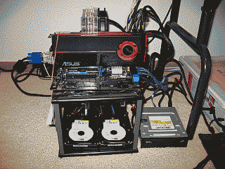
Figure 1
I decided to get a new power supply for this rig. The existing PC Power & Cooling Silencer 750 that I originally intended to use for this upgrade I felt could best be used elsewhere. I’m partial to the single 12 VDC rail design for PC power supplies so I ended up picking up Corsair’s’s 750TX.
Intel offers several methods for updating their BIOS, including updating directly from the OS using a utility called “Express BIOS Update.” Sans OS though, your choice is to use Intel’s tried and true “IFLASH2” utility and the BIOS file from a bootable floppy, USB or optical disk, or use a bootable ISO image to update the BIOS firmware. I chose the latter and it was a breeze. Burn the image to a CD-R, boot to it, and in 5 minutes your BIOS firmware is updated.
In order to build the RAID arrays, I navigated to Advanced -> Drive Configuration -> Configure SATA and made sure that the RAID option was selected, then rebooted and entered Intel’s Raid configuration utility (using CTRL-l). I chose the default stripe size of 128 KB for my two RAID 0 arrays. Returning to the BIOS, I made some additional preliminary tweaks before installing the OS, including disabling the 1394 port (never use it), disabling CPU and System fan control (I prefer to run them wide open), and turning off the Event Log (this is a feature?). Adjustments to Performance section of the BIOS will be saved for when I start overclocking the system. I then booted into Memtest86+ (v4.00) and ran it for 2-3 passes to verify that the RAM was solid. Sweet, no errors.
Windows 7 comes with native support for RAID, so rather than choosing to install my own via the usual “F6” method I let Windows use its own. After the OS was fully operational though, I installed Intel’s RAID driver, as well as the essential audio, LAN and graphics drivers; activated the OS and downloaded Microsoft updates. I then installed applications and performed the my usual OS performance tweaks. With the exception of a few applications, such as Guild Wars and Quake 3 Arena, which I made run using compatibility mode, all my applications installed and ran just fine on Windows 7 Pro 64-bit.
My Canon i560 printer had me scratching my head though. First, Canon’s Windows 7 64-bit driver for the i560 does not work; and, to complicate things, my printer is parked on a D-link print server. To install a driver that would allow this PC to see the printer, I first had to connect the printer directly to the PC via USB. Then, instead of messing further with the flaky Canon driver, I let Win 7 find and use its own native driver. Then I deleted that printer and put the printer back on the print server. I created a new printer, but this time configured for a proper TCP/IP port. When it came time to load a driver, I simply reused the one Win 7 added when the printer was directly connected.
The Temp
Almost immediately after I get a new system up and running on the bench I navigate to the BIOS’s hardware monitor to verify the temperature(s) it’s reporting for the CPU so as to ensure I have the heatsink and fan installed and working correctly.
Back in the good old days (you know, before Core i7), you would typically pay attention to the “CPU temperature” the motherboard was reporting. This is the processor’s Tcase temperature, the temperature at the geometric center of the topside of the integrated heat spreader as measured (or estimated) by a sensor IC. This temperature value is routinely used by utilities such as Everest, SpeedFan, as well as ones provided by the motherboard manufacture, to report the thermal condition of the processor. According to Intel, Tcase should be maintained at or below the thermal threshold listed in the processor’s datasheet. For the Core i7 860 processor for example, that value is 72.7C. Given a reasonably accurate measurement of Tcase and the not-to-exceed threshold value provided by Intel, you knew exactly where you stood with respect to your processor’s temperature.
Enter core temperatures. Unlike Tcase, the processor’s core temperature is the temperature measured by the processor’s Digital Thermal Sensor (DTS). This value is always relative to what Intel feels is the maximum core temperature threshold for a given processor model, a parameter Intel calls TjMax. Nominal core temperature values, as reported by utilities such as Core Temp and Real Temp, would be an equally reliable way of representing processor temperature if you knew with certainty the value of TjMax. Knowing that value would provide you with a fairly reliable way to calculate your core temperature, and by extension, how much margin you have before encountering TjMax:
Core Temperature = TjMax – DTS reading
Unfortunately, Intel treats the TjMax value as if it were a matter of national security, and so these utilities are left to essentially guess what the TjMax value is in order to report the nominal core temperature values. In other words, core temperatures, while nice to know, aren’t terribly useful because: 1) Their accuracy is suspect; and 2) there is no direct correlation to the nominal value of Tcase and it’s threshold as provided by Intel in the processor’s specification.
On the Intel DP55KG that I’m using for this upgrade, the situation seems to have gotten even murkier. On this motherboard there are two temperature readings reported in BIOS: Internal and Remote. Instead of Tcase, this Internal temperature is apparently meant to represent the processor’s core temperatures. This was confirmed when, after installing Real Temp, the temperatures reported by that utility matched the one reported by the BIOS within about one degree. Speedfan’s readings also closely matched these readings. And the “Remote” temperature reported by the BIOS? Since it routinely reports temperatures 2-5 degrees below those reported by the Internal reading, I suspect its readings come from a thermal sensor near the processor, whose job it is presumably to keep track of the internal case temperature.
It appears then that Intel now seems to be more interested in focusing on core temperatures and their relative difference from TjMax. But how does this help me ascertain how much headroom I have with respect to the Core i7 860’s thermal profile value of 72.7C? In short, it doesn’t. So I guess I’ll need to trust that Intel will keep the processor from exceeding whatever it feels are its critical thermal thresholds, Tcase or otherwise. My job, it appears, is merely to keep the core temperatures as low as possible.
The DP55KG’s BIOS was reporting that the processor’s core temperature was idling at ~36C (ambient room temperature is routinely ~20C). I felt I could probably do better than this so I went in search of a heatsink to replace the Arctic Cooling Freezer 7 Rev.2 I was using for this build. As mentioned in my initial post, even finding a suitable heatsink for an LGA1156 CPU was a challenge. While there were plenty of options for 1366-based boards at the time I was pulling the parts together for this build, very few of the more reputable heatsink manufactures had yet to put out parts made specifically for with newer LGA1156. The second time out though I ran into a Maximum PC article regarding the Cooler Master Hyper 212 Plus air cooler.
I picked one up, replaced the Freezer 7, and was able to lower the idle temperature to 30C. Needless to say I’m quite happy with it. As you can see though, the heatsink does land very close to the RAM modules (See Figure 2).
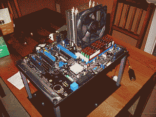
Figure 2
This brings up another issue that would be a good to mention here and that’s the best procedure I found for applying the thermal compound. Arctic Silver suggests applying their Arctic Silver 5 product in a line over the CPU heatspreader horizontally, but not spread the line out. Instead, when you place the heatsink on top of heatspreader of the CPU, the line of Arctic Silver 5, they suggest, will “spread out just like an oval pancake.” Well, it did spread out a bit and it may resemble an oval pancake (See Figure 3), but this method does not yield the best results. I tried several variations of this pancake method and compared the results with the more traditional method of placing a small amount of compound in the center of the processor and spreading it thinly and evenly so it covers the entire top of the processor, and in each case the latter method produced the best results.
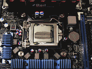
Figure 3
I think the problem with Arctic Silver’s method is that it actually places too much compound on the processor resulting in poorer heat transfer, not better. But perhaps a more significant factor leading to poorer results in my case is the unique design of the Cooler Master 212’s heatsink itself. Instead of the typical smooth copper surface, this heatsink is built in such a way as to allow its heat pipes to rest directly on the processor. Consequently, the heatsink surface is not smooth but instead has ridges where the heat pipes nestle against a nickel plate. These ridges seem to be preventing the thermal compound from spreading out as well as Arctic Silver intended (See Figure 4).
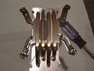
Figure 4
Final Thoughts
After putting each of these speed bumps behind me I was ready to place all of the components in the NZXT Tempest mid tower case. I decided to forego using the case’s side fan in order to improve positive air flow, but even with one less fan, it was immediately apparent that I was going to run out of fan headers. No worries though, I typically run the fans wide open anyway so I simply wired 12VDC to each of them. The Tempest isn’t the easiest case to dress up wiring in but I managed hide some of it behind the motherboard (See Figure 5).
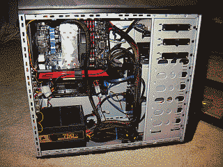
Figure 5
In the next post I’ll share my experiences with overclocking the DP55KG and Core i7 860.


