(20171231 — The steps in this post were amended to address changes in recent versions of software. Minor editorial corrections were also made — iceflatline)
pfSense is a customized version of FreeBSD tailored specifically for use as a perimeter firewall and router, managed entirely from a web browser or command line interface. pfSense includes a long list of other features, as well as a package system allowing its capabilities to be expanded even further. pfSense is free, open source software distributed under the BSD license.
A VLAN (“Virtual Local Area Network”) is a logical grouping of network hosts (and other resources) connected to administratively defined ports on a switch. This enables hosts to communicate as if the attached to the same physical medium, when in fact they may actually be located on different LAN segments. A VLAN is treated like its own subnet or broadcast domain, which means that Ethernet frames broadcast onto the network are only switched between the ports logically grouped within the same VLAN.
In this post I will describe how to create and configure a VLAN in pfSense. Once configured, you’ll be able to route (or prevent routing) traffic between this VLAN and other VLANs, and each VLAN will be able to share the same Internet connection. To help explain the steps involved, we’ll create a static VLAN on a 24-port switch and trunk that VLAN from the switch to the LAN interface on pfSense, where we will assign the VLAN a unique /24 private IP subnet.
All steps involved assume that: 1) pfSense is installed correctly and providing basic Internet connectivity to an existing LAN interface; 2) the NIC (“Network Interface Controller”) assigned to the LAN interface supports IEEE 802.1Q VLAN tagging; and, 3) the switch connected to the LAN interface is capable of supporting the creation, configuration and trunking of port-based VLANs.
The software versions used in this post were as follows:
- 2.4.2-RELEASE-p1 (amd64)
The switch used in this post was a Cisco model SG200-26; a so-called “smart switch,” featuring, among other things, Gigabit Ethernet, a web-based management interface, and simultaneous support for up to 256 port-based and IEEE 802.1Q tag-based VLANs.
Each switch, and its associated management interface is different; therefore, you’ll need to make the appropriate adjustments when following the instructions in this post in order to successfully configure your particular switch.
Let’s get started…
Configuring the Switch
As you may recall, static VLANs, often referred to as “port-based” VLANs, are created by assigning switch ports to a preconfigured VLAN identifier. In this example, we’ll configure a static VLAN on our switch and assign it VLAN ID 50. Note that you can use any positive integer between 2 and 4094 you’d like for your VLAN ID, however, VLAN IDs 1 and 4095 should be avoided because, as a general rule, most switches by default assign all ports to VLAN ID 1, the “administrative” VLAN ID, and VLAN ID 4095 as the “discard” VLAN.
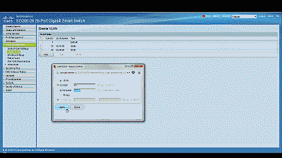
Begin by navigating to VLAN Management->Create VLAN and select “Add.” Enter a value of 50 in the “VLAN ID” field and enter a name to denote this particular VLAN in the “VLAN Name” field. In this example, we’ve used the name “vlan50.” When complete, select “Apply”. (See Figure 1)
Before assigning membership of a particular port to our new VLAN, we must first configure that port to be either an “Access” port or a “Trunk” port. Access ports are ports that are members of only one VLAN. This type of port is normally used for attaching end devices which are generally unaware of a VLAN membership, either because their NIC is incapable of tagging Ethernet frames a VLAN ID, or they are not configured to do so. Switch ports configured as Access ports remove any VLAN information from the Ethernet frame before it is sent to the device. Trunk ports on the other hand can carry multiple VLAN traffic, and are normally used to connect switches to other switches or to routers. It is very often the case that small-business grade switches, such as the Cisco SG200, designate each port as a Trunk port by default.
To keep our example simple, we’ll assume that the device(s) connected to the switch are not configured, or are unable to be configured, to tag Ethernet frames with a VLAN ID. Consequently, in this example, we’ll configure port 19 as an Access port, and assign it membership in our newly created VLAN. Furthermore, we’ll also assume that port 25 is currently being used to connect the switch to the pfSense LAN interface, and configure it as a Trunk port, assigning it membership in our newly created VLAN.
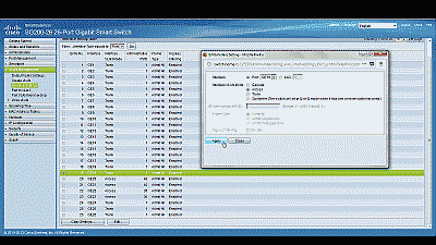
Navigate to VLAN Management->Interference Settings, select port 19 and then select “Edit”. Change the Interface VLAN Mode from Trunk to Access, then select “Apply” (See Figure 2). Now follow similar steps to configure port 2 as an Access port.
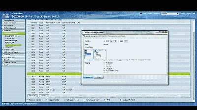
Next, navigate to VLAN Management->Port VLAN Membership, select port 19 and then select “Join VLAN”. Since Access ports can be added as untagged to only a single VLAN, we’ll need to first remove the default VLAN the switch automatically assigns to each port (usually VLAN 1). Highlight VLAN 1 by left-clicking on it, then select the arrow icon to remove it from the interface. Now highlight VLAN 50 by left-clicking on it, then select the arrow icon to add it to the interface, ensuring that “Untagged” is selected from among the options under “Tagging”. Select “Apply” when completed (See Figure 3).
With switch port 19 configured as an Access port and joined to VLAN 50 any Ethernet frames that enter that port will be tagged with the appropriate VLAN ID. Now let’s configure the port 25, the port that is connected to the LAN NIC in pfSense. This port will be configured as a Trunk port and joined to VLAN 50 so that, in addition to passing the Ethernet frames from from devices attached to the other ports on the switch to pfSense, it will also pass Ethernet frames tagged with VLAN ID 50 entering switch port 19.
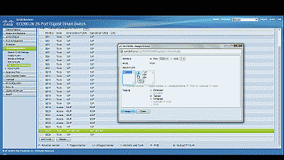
Ensure that port 25 is configure as a Trunk port, then navigate to VLAN Management->Port VLAN Membership, select port 25 and then select “Join VLAN”. Highlight VLAN 50 by left-clicking on it, then select the arrow icon to add it to the interface, ensuring that “Tagged” is selected from among the options under “Tagging”. Select “Apply” when completed (See Figure 4).
That’s it for configuring the switch. If your switch supports both a running configuration and a startup configuration, make sure to save the changes you’ve made to the startup configuration so that they are not lost should the switch reboot for any reason.
Configuring pfSense
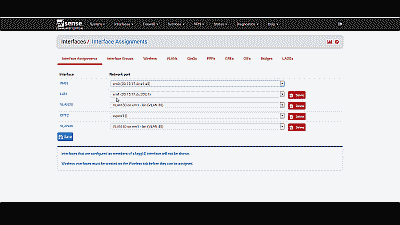
Now we need to create and configure VLAN 50 in pfSense. Navigate to Interfaces->Assignments and make note of the device driver name assigned to the LAN NIC. For this example we’ll assume the device driver name is “em1” (See Figure 5). The LAN interface will serve as the “parent interface” for the VLAN interfaces we will create in the next step.
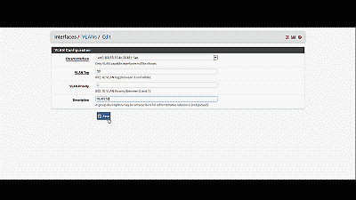
Next, navigate to Inerfaces->Assignments->VLANs and select the “+ Add” icon. In the subsequent screen, select “em1”, the LAN NIC interface, from among the options in the drop down list under “Parent interface”, and enter the value of 50 under “VLAN tag”. Add an optional description for this VLAN under “Description”, then select “Save” (See Figure 6).
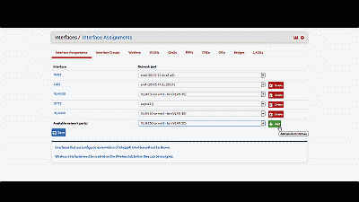
After creating the VLAN interface, return to Interfaces->Assignments and select the “+ Add” icon to add the “VLAN 50 on em1-lan (VLAN 50)”, then select “Save” (See Figure 7). At this point you’ll notice that under the “Interface” column pfSense has likely denoted VLAN 50 as an optional or “OPT” interface. Don’t worry, we’ll address that next.
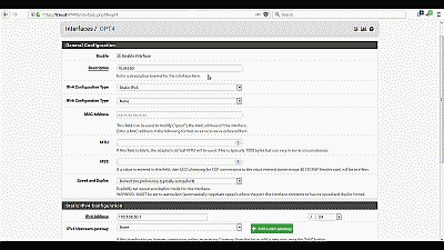
For this example we’ll assume that pfSense has assigned VLAN 50 as OPT4. Navigate to Interfaces->OPT4 and select “Enable Interface”. Under “Description” replace “OPT4” with “VLAN 50”, then select “Static IPv4” from among the options in the drop down list under “IPv4 Configuration Type”. We’ll use network 192.168.50.0/24 for VLAN 50 by assigning the static IP address 192.168.50.1 on this interface, and selecting the network mask of “24” under the “Static IP Configuration” section. The other parameters can remain at their default values. Select “Save” and “Apply changes” when complete (See Figure 8). Now if you navigating back to Interfaces->Assigments you will see VLAN 50 listed and labeled with the description you added when enabling the interface in the previous steps.
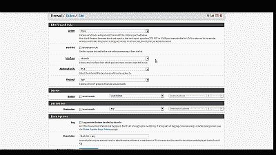
Next, we need to build a firewall rule for our two new VLANs so that traffic can pass to / from the WAN interface, and by extension, to the Internet. Navigate to Firewall->Rules and select the VLAN 50. Select the “Add” icon (there are currently no rules so either Add icon will work) to create a new rule. For our example, we’ll build a simple outbound pass rule for any protocol in VLAN 50, similar to the way a typical LAN outbound pass rule would be configured. Select “any” from among the options in the drop down list Under “Protocol”, and under “Source” select “VLAN50 net” from among the options in the drop list. If desired, you may enter a description of this newly created rule for your reference under “Extra Options”. The other parameters can remain at their default values. Select “Save” and “Apply changes” when complete (See Figure 9).
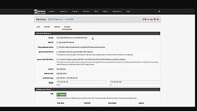
Unless you plan to assign static IP addresses to host devices, you’ll want to configure a DHCP server for the new VLAN 50. Navigate to Services->DHCP server and select VLAN 50. Select “Enable DHCP server on VLAN50 interface”, then enter the range of IP addresses within the network 192.168.50.0/24 you’d like the DHCP server to use under “Range”. Finally, pfSense will use the IP address assigned to this interface as the gateway address by default. For our example this address will be 192.168.50.1. If your requirements call for something different, enter an IP address for the network gateway under “Gateway”. The other parameters can remain at their default values. Select “Save” when complete (See Figure 10).
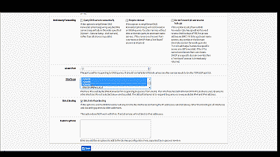
You’ll also want to navigate to Services->DNS Forwarder->Interfaces and ensure that interfaces used by the DNS Forwarder for responding to queries from clients includes VLAN50, then select “Save” and “Apply changes” when complete (See Figure 11).
Wrapping up
At this point the LAN switch and pfSense should be configured to support VLAN 50. To test, connect a host device such as a desktop or laptop computer to port 19 on the switch. If you’ve configured everything as described, you should receive an IP address within the DHCP address range you’ve specified for VLAN 50 network 192.168.50.0/24. The default gateway, DHCP server and DNS server addresses should be 192.168.50.1. You should also have Internet connectivity.
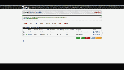
Be aware that as currently configured, each VLAN is routed to all other VLANs. If you would like to disallow some or all traffic to/from a particular VLAN you must create firewall rules explicitly stating what traffic should not be routed. Keep in mind that pfSense evaluates firewall rules on a first-match basis (i.e. the action of the first rule to match a packet will be executed). So, for example, if you wanted to block all VLAN 50 traffic from reaching the LAN you might create a rule to that effect before the one we created previously to route all VLAN 50 traffic to any destination (See Figure 12).
Conclusion
VLAN support in pfSense is not hard to configure nor complicated to manage, assuming your switch and NICs support this capability. To help explain the steps involved, we created a static VLAN on a commodity 24-port small-business switch and trunked that VLAN to the LAN interface on pfSense. We then created and added the VLAN interface, created the requisite firewall rules, and assigned the VLAN a unique /24 private IP subnet with host addressing handled using DHCP. The VLAN is able to share the pfSense’s Internet connection and we are able further configure pfSense to prevent routing traffic between each VLAN, if desired.
Great Job…. you save me a lot… Thank you very much… :)
Question, what IP did you set the PFSense firewall to?
I ask because I am trying to wrap my head around my configuration.
My pfsense is 192.168.5.254
My main lan is vlan5 or 192.168.5.0/24
My subnet 10 or vlan 10 is 192.168.10.0/.24
My subnet 20 or vlan 20 is 192.168.20.0/24
I set my trunk port to tag all vlans 1,5,10,20
When I do set the uplink port to my pfsense to tag all these ports, I loose connectivity to the pfsense firewall.
Any help is appreciated.
Joe: In the example in the post, the LAN IP network was configured to 172.20.0.0/20 and the PfSense machine’s address to 172.20.0.1.
Unfortunately, without knowing more about your configuration, it’s difficult to say where your problems may be occurring. However, you mention that you’re tagging VLAN 1 on the uplink port. Normally this is the administrative VLAN ID and you need not / should not assign it as usable VLAN ID. Are any of your access ports setup to tag incoming traffic with VLAN 1. If not, none of the incoming switch traffic on those non-VLAN 10 and 20 ports will be uplinked.
Thank you it work the very first time. I substituted the cisco for netgear vlan switch and change the vlan tags to 1, 2, 3 etc and they work perfectly.
Truly appreciate your effort and it works :)
Moskaluk, you’re welcome. It’s great when things just work.
[…] are the basic to start u off: – https://teksyndicate.com/videos/pfse…pc-epic-router – How To Create And Configure VLANs In pfSense | iceflatline These will pushing your test&trial sanity! – 从源辞典 » Blog Archive » Cisco SLM2008T […]
Good job! thank you very much
Hi,
I just (21.07.2014) did an office setup with 4x Cisco SG200-50p and 2x Netate (pfSense 2.1.4) C2758 and I have to say that indeed setting up VLANs with pfSense and the Cisco SG200 series is simple (as described in the above guide) and cost effective.
Martin
Martin, pretty sweet setup. Thanks for sharing.
you said that there is already routing enabled for this VLAN, right? on my setup, if i don’t set the GW to another route(pointing to my other WAN connection) routing between VLAN works but if it set it to exit to another gateway routing between VLAN seems broken… hopefully this make sense… :)
do you have this issue?
ncurses, I do not have dual WAN connections, so no, I have not encountered that issue.
Well explained!!
i have vlan 1 as the default vlan in 10.0.0.1/8 subnet and i have installed pfsense and now want to shift my network to vlan environment .. so i start creating vlan 10, 12, 13, and so on.. and still i have vlan 1 also .. i have main switch foundry bigiron 8000 which the facility of dual mode per port which help in traffic transfer of both tagged as well as untagged .. so my vlan work fine but the problem is traffic from untagged to tagged vlan can not be passed …. kindly help me to resolve this problem….
i want traffic from vlan 1 to be passed to vlan 10 12 13 etc and vice verse …
sraza, it’s going to be difficult to offer you much help here. I’m not familiar enough with your particular network setup or switch. As a general comment though, you’ll want to make sure that when LAN traffic comes into the ports you’ve selected for VLANs, those ports are tagging traffic with the correct VLAN ID. You’ll also want to ensure that traffic is exiting the port connected to the pfSense box tagged with those same VLAN IDs, including the default VLAN 1 ID. By default, pfSense will route traffic between the all VLANs. If you don’t want that to happen, you’ll need to create firewall rules explicitly stating what traffic should not be routed.
I would further suggest doing a little ‘Googling’ to see if there are some unique setup concerns with your particular switch.
Great article was excellent in helping me set up vlans. Appreciate VERY MUCH the effort put into creating this, thank you.
John
John, awesome. Thanks for the kind words. Glad it was helpful.
John – is there a way to monitor and graph traffic per vlan ?
Jared, if you navigate to Status->RRD Graphs you should find your VLAN(s) in the drop-down list associated with the Graphs: field
Just so I have this right, this is what the LAN looks like:
em2 Physical NIC – 172.20.0.1/20 – DHCP disabled?
VLAN10 on em2 – 192.168.10.1/24 – DHCP enabled
VLAN20 on em2 – 192.168.20.1/24 – DHCP enabled
Do you have to give the physical NIC an IP, or can you just give IPs to the VLANs? If not, is there a benefit to giving the em2 NIC an IP? Is there a way to have pfSense tag untagged packets to default to VLAN10 or 20? I have little experience with setting up VLANs. I’ve done little work with them on Cisco UC devices using CCA, so I’m just trying to wrap my head around this concept.
This is a great article, and I thank you for posting it. It has helped me a lot.
Best regards!
Jason, the configuration you’ve provided looks correct to me. As to whether or not you can just provide IPs to VLANs, I don’t know for sure. Usually the LAN NIC is already assigned an IP (usually the first host address in that subnet). You’ll have to experiment. With respect to tagging, pfSense will automatically tag packets appropriately.
Sound good to me. Thanks for the quick response! Like you say, I’ll have to check it out when I get a chance.
it is the only work that well explains the configuration of pfsense and switch. includes the theory necessary to know what you’re doing. and everything works ok after doing so. my congratulations and a big hug from Argentina
[…] I configured a VLAN on my LAN port of my pfSense box and called assigned it an ID of 10 like the article said. […]
I followed your instructions to the letter. I am still having problems. I am using a Netgear WNDAP330 as a wireless access point. There is a private SSID which is on our 10.10.x.x corporate subnet and I’m trying to get another SSID for guest WIFI. The SSID is called GuestAccess and is configured on VLAN ID 5 with a network subnet of 192.168.5.0/24. DHCP is enabled on the WNDAP330. The switch port (GE18) on Cisco managed switch is a member of VLAN 5, tagged. The port the pfsense box is on is also a tagged member of VLAN 5.
The interface is not seeing any traffic. Not sure if DNS is working. Wireless clients connect, but can’t get to the internet. Can you help? Ask any questions you need to get the information you need to help.
Tony, I have a similar setup. I have a wi-fi access point on a separate VLAN for guest use. However, instead of the allowing the AP to provide DHCP support or act as the default gateway, I have it configured to simply act as bridge. As such, the pfSense box is the default gateway for all clients connecting to the AP, and the IP addresses are provided by the DHCP server configured on pfSense for that VLAN. The problem you may be having is that your AP may still acting as a default gateway, and so may not be properly configured to route traffic upstream to pfSense. To start troubleshooting you may want to remove the AP and connect a PC or laptop directly to that switch port and see if you can connect.
Hi… Your post is very great… I need to make vlan on my pfsense but to do balancing in my pfsense. So.. I have 9 DSL. One Pfsense Server with an additional NIC 10/100/1000mbps Tplink. I havent prove this configuration to do that i want. Will it work great with this configuration but connecting in wan port instead of lan port? I wanna create 9 Vlan to plug 9 DSL to do balancing in pfsense. Will work your steps? Thanks…
Enyerberth, I do not know. I suspect you could set it up that way but I’m not sure how well pfSense will load balance across that many WAN interfaces. Why do you need so many?
currently i have 2 loadbalancer Tplink 470+ with 4DSL Each LB. Each DSL has 10MB but the LB doesnt get it. They dont work well. Just get 4MB and their balancing is not stable, because of it i wanna balance directly by pfsense but my server just has 3 additional NICs and i need 8 and because of that i wanna set my cisco switch up as VLAN for my 8 DSL . Do you understand to me ?
Understood. Let me know if and how it works.
Nice… I will be gratefull if you could help me..
Thanks so much for this very helpfull post. I followed all your indications. I encountered a problem. This is what the LAN looks like:
em0 Physical NIC – 192.168.77.1 – DHCP enabled
VLAN10 on em0 – 172.10.0.1 – DHCP enabled
One laptop connected to one access confirgured port of my SF300 cisco. I get the first IP delivered by the DHCP Vlan10. Port 24 of the Cisco switch as a trunck port (1U,10T) and rules configured I cannot reach Internet.
Any help will be appreciated. Thanks in advance.
enzo, thanks for your comment. Without access to the equipment it’s difficult to say. If you’re getting an IP address from the VLAN’s DHCP server, it sounds like you may not have the firewall rules setup properly, or perhaps something else, in order to pass VLAN traffic to the Internet.
If your laptop NIC supports VLANs you might try adding it to VLAN 10 and connect it directly to pfSense em0. This way you could at least eliminate the switch as the source of the problem.
Hello iceflatline, thanks so much for your response. I found the origin of my problem. In fact,Vlan10 traffic pass to Internet if I only disabled the portal captive Lan I have configured. This PF autentification functionnality, thrue Radius server, works fine and at the moment only with my Lan em0 trafic. I’ve tried to fix that problem with one more captive portal enabled for Vlan10 but unsuccessfull. Maybe some ports rules adjustments are needed . I’m triying to fix that problem. Any idea will be most and in advance welcomed. Regards
enzo, I suggest posting your questions at the pfSense forums or in their IRC channel.
I guess my problem comes from this rule : “PFsense captive portal can only run on one interface at a time.” In that case, what would be the solution for getting Vlan10 clients authenticated ? Thanks.
There is a typo, there is no pfSense v2.3.2 yet.
logicwon. Thanks. There is indeed. Should be 2.1.2. Fixed.
As far as I know,
when using vlan with pf (manage the vlan subnets), you cannot use the vlan physical host interface as LAN (physical interface). there is a great troubles up to failure if you try to config vlans with a single host interface (LAN interface).
In summary : let’s say you have,
em0 = external interface (WAN)
em1 = internal interface (LAN)
If you must need to configure vlans, see to it never use the physical LAN, use the vlan em1_VLAN10 as your LAN, em0_OPT = WIFI and so on.
so it is why from pf devs, they recommend use another extra interface to handle the vlans and leave the LAN interface alone for pf management, or for another separate use. You may feel the need of immediate access to PF’s gui that interface is a big and great escape from disaster you must face with vlans.
………………..
[…] https://iceflatline.com/2013/09/how-to-create-and-configure-vlans-in-pfsense/ […]
[…] I configured a VLAN on my LAN port of my pfSense box and called assigned it an ID of 10 like the article said. […]
Thank you so much! Very helpful!
Thanks Scott, you’re very welcome.
Very helpful article for setting things up. I do have one dilemma that perhaps someone here can help me with. My configuration is as follows:
em0 – WAN
em1 – LAN (labeled VLAN1 (default), untagged or access, connects to switches)
opt1 – VLAN 2 on em1 (used for server data, tagged or trunk)
opt2 – VLAN 3 on em1 (used for general network data, tagged or trunk)
Here is my issue. Currently, both VLAN 2 and 3 are able to communicate with eachother and able to access the internet. However, they cannot access the switches which in theory should be connected directly to the LAN port and use an untagged or access connection. I would like to be able to access the switches via telnet from my computer(s) or server(s) which are connected to switch ports assigned to their respective VLANs. My question: How can I get VLAN 2 and 3 to be able to communicate with devices on the LAN interface? I would imagine it is just a firewall rule I have to add, but I have tried and tried and can’t figure it out.
Any help is appreciated. Thank you in advance!
As of right now I have a switch port that is untagged/access on the default VLAN to which I manually connect a computer when I need to telnet to the switches.
Thanks so much for the article. I am almost set for the pfsense portion but am having an issue.
I am using a very similar switch to you (Cisco SG300 10 Port) same software.
When i perform the Vlan Membership portion (figure 4) I have no mode for Port1 (GE1) and have no vlans to move left or right? The pop up screen is basically empty with the exception of interfaces.
has anyone seen this before?
Jacob, Have you tried a different browser? I had a similar issue recently. Firefox would not show the contents of that pop-up window, but Google Chrome would.
Typo I think:
“Follow similar steps to configure the DHCP server for VLAN 20, this time entering a range of IP addresses within the network 192.168.10.0/24, and 192.168.20.1 as the IP address for the network gateway.”
Should be “…network 192.168.20.0/24”
Thanks for the great article! Maybe you can have a network diagram?
Fuzz, good catch! Thanks very much for letting me know. It has been fixed. Adding a network diagram is a good idea. I’ll see what I can come up with.
This almost worked but I couldn’t get the outbound traffic to reach the internet. It seems the problem was that a NAT rule is need in addition to the firewall rule described here. I assume that rule is created automatically when your mode is set to automatic, but I had mine set to AON on the Firewall NAT page. Once I created that rule, routing the VLAN network to the WAN address, everything worked fine.
EricT, thanks for the comment. I have no such outbound rule in my configuration (pfSense version 2.3.1) and it seems to work fine. I now wonder if mine works only because it was upgraded from earlier versions, whereas a new install may indeed require an outband NAT setting. I’ll see if I can setup a test system and experiment.
Thank you,
my scenario is as follows.
From the router,we have one Internet source. So I use Pfsense as the router, its basically a desktop computer running pfsense inside.It has two NIC Cards, (for the WAN and the other one for the LAN) that goes to the switches.
In total we have 5 dlink switches, interlinked to one another.
From the Dlink switches, 4 access points connects to them.This access points are the WAP200 type and they have support for multiple SSID.
So what I intend to achieve is, create 2 VLANS, one for the staff i,e those who print, work here etc and the other VLAN for those guest who visit us occasionally.
Guest who visit basically need internet only via WiFi.
As such in the WAP 200, I have created 2 SSID’s, the guest wifi ought to be in a different network from the corporate one,(existing one)
I thought i have to configure VLAN’s from the router, and the respectively to the switches, right?
so that traffice tagged for VLAN 20 in the router goes to VLAN 20 in the switches, right?
the other issue was for the access points, considering the access points has multiple ssid, how do i ensure SSID 1 gets traffic from VLAN 10 and SSID2 gets internet/traffic from VLAN 20
thank you and kind regards
Kefa, Thanks for your comment. Creating two VLANs – one for guest WiFi – is a good way to configure your network. I have a similar configuration. In my case, however, I use one access point for normal LAN access via WiFi using a single SSID, and another access point for guest WiFi access, with a separate SSID, over VLAN 20. If your access points – supporting two SSIDs – can tag traffic from each SSID using separate VLAN IDs then it should not be a problem setting this up as you’ve described. In this case you’ll want to configure the switch port they are connected to as Trunk ports supporting the two VLAN IDs you’ve configured at the access points. However, if the access points do not support VLAN tagging, then you’ll likely have to dedicate a single access point to each SSID then tag incoming traffic coming from them at the switch port as described in the post.
Dear ,
please find my scenario is as follows.
i have 2 nos of ISP internet links . 2 nos pf core switches & 4 nos of distribution switches .All trafics are routed to core1 then firewall for internet . near about 3000 users inside my network . there are 30 nos of vlans are created in my distributions . is it possible that we can use pfsense for internet users inculding wifi users . i have extra Dhcp server & proxy server also.
please suggest me or email-me.
Laxmi, yes it should be possible. You may even wish to add a second pfSense machine for redundancy. However, I would also suggest you discuss your configuration with the pfSense community to determine whether there are additional configuration options you should consider – 3000 users is a lot of users. The pfSense forums and IRC channel is a good place to start.
Thanks a lot!
Learned how to set up vlans today based on this post! Fantastic guide! ;-)
Keep it up!
/Grateful SOB
Regarding conversation with EricT (2016 Jul 31) about outbound rules on VLAN. I’ve just finished a lab setup which required changing from two LAN connections to the switch, to one 802.1Q trunk connection. I did have to install outbound rules for each VLAN to even connect to the switch.
It was a great tutorial! THANK YOU!!
Used this guide to help me get my 3COM switch ==> Single Modem ==>virtual pFsense.
All with a distributed vSwitch. Now I can vMotion pFsense without dropping a packet.
telserv_ca, okay thanks for that information. As I replied to EricT I currently have no such rules but that was on an earlier version of pfSense that has since been upgraded. I still hope to duplicate the setup on a fresh install. Sounds like based on your experience that outbound rules will be required, in which case I will need to clarify in the post.
Thank-you-very-much, awesome. Glad it helped.
I have a problem here.. it can’t do the intervlan. different vlans cannot ping to each other
glomm, thanks. It’s been a awhile since I wrote this post so I will need to test the steps again. I’ll do so as soon as I can. I can’t help but wonder if explicit rules are now needed in the firewall in order pass traffic between VLANs.
Wonderful work. Thanks. I see your articles and boy, you have a way of explaining stuff. Thanks for helping the diy world at large. Truly appreciated
p
answering glomm, there are no explicit rules that need to be put into the firewall rules to pass traffic from one vlan to the other. Since the vlan interfaces are on the pfsense router, routes are already known, so there is not issues with intervlan routing. It is on by default. If windows clients are the ones that you seem to have problems with, then try disabling the firewall or putting in a rule in the firewall for icmp or other protocols. should work.
thanks
p
Praveen, thanks for the kind words as well as the advice.
Excellent write up, thanks for taking the time and explaining all the steps in such detail.
You say:
“We’ll use network 192.168.50.0/24 for VLAN 50 by assigning the static IP address 192.168.10.1 on this interface…”
Presumably 192.168.10.1 should instead be 192.168.50.1.
Hi Pete. Yup. Thanks for catching that. The error has been corrected.
(OPNsense = PFsense)
All right, thank you
I tried, but I no longer had internet access.
The physical LAN interface should be left? Or not?
If so, I do my VLAN interfaces “” tagged “” On this physical interface and then the rules?
= > http://www.noelshack.com/2018-26-1-1529940529-2018-06-25-17-27-50-echidna-intrasense-fr-interfaces-assign-network-ports.png
So (if the interface “main ” must be left), if I want to stay on the same addressing for VLAN 10 as the previous LAN (192.168.1.0/24), I have to assign another addressing to the physical interface for the VLAN 10 interface to have this 192.168.1.0/24 Network?
Otherwise, possible causes could be:
-I may have made bad rules of FW, and because of this, Internet access did not pass…-or the network card of the server is “Old “, and so the VLANs do not pass. I can not say, I am recently in the company and no view on the dates of purchases, but it would be a real pity:(
PS: Changes are snapshots when I click on “Apply changes “, or you have to restart OPNsense/PFsense each time?
[…] Source: http://www.iceflatline.com/2013/09/how-to-create-and-configure-vlans-in-pfsense/ […]
Thank
it was just what I was looking for
[…] iceflatline – How To Create And Configure VLANs In pfSense […]